
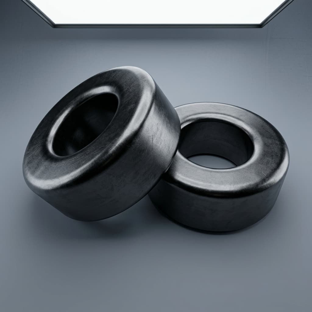
SmCo Magnet Assembly Risk Control: Preventing Chipping and Cracking
Engineering and procurement guide to reducing assembly scrap, preventing SmCo magnet chipping, and choosing safer integration methods for OEM builds.
When engineering teams migrate from Neodymium (NdFeB) to Samarium Cobalt (SmCo) to unlock higher thermal headroom, they often encounter an unexpected and expensive hurdle on the manufacturing floor: massive assembly scrap rates.
SmCo magnets are exceptionally brittle. Without proper handling protocols and geometry optimization at the procurement stage, it is not uncommon for OEMs to experience a 10% to 20% scrap rate during pilot builds due to chipping, cracking, or catastrophic shattering. This guide provides a comprehensive framework for buyers, manufacturing engineers, and quality teams to control these risks from the initial RFQ down to the assembly line.
Scope and review basis: This article was reviewed on 2026-06-24 for global OEM procurement and assembly teams working with sintered SmCo5 or Sm2Co17 magnets. It focuses on mechanical breakage during handling, shipping, bonding, clamping, sleeving, and press-fit operations; it does not replace a formal finite element stress review, supplier drawing approval, or local EHS procedure for magnetic materials and combustible dust.
The Hidden Cost of SmCo Brittleness in Manufacturing
While SmCo delivers unmatched stability at extreme temperatures (often up to 350°C for Sm2Co17 grades) and excellent natural corrosion resistance, its mechanical properties are its Achilles' heel. The material lacks fracture toughness.
For procurement teams, this brittleness introduces hidden costs that do not appear on a standard magnet quotation:
- Direct Scrap: Broken magnets that must be discarded.
- Rework Labor: Time spent extracting chipped magnets from glued or press-fit assemblies.
- Contamination Risk: Magnetic chips migrating into bearings, stators, or sensitive electronics, leading to catastrophic system failure in the field.
- Delayed Timelines: Having to re-order custom magnet batches because the initial pilot run was destroyed during integration.
Understanding and mitigating these risks requires a joint effort between the sourcing team writing the specifications and the manufacturing engineers designing the assembly process.
Why SmCo Chips More Easily Than NdFeB
To understand the assembly challenge, we must look at the mechanical differences between the two leading rare-earth magnets. While both are manufactured via a powder metallurgy sintering process, their crystal structures yield different mechanical behaviors.
NdFeB is relatively tough for a ceramic-like material. It can often survive light impacts and moderate press-fitting without edge failure. SmCo, conversely, has a significantly lower tensile strength and fracture toughness. It behaves much like glass or advanced ceramics.
When a fully magnetized SmCo part approaches a ferromagnetic stator or another magnet, the attractive force can cause the components to "slam" together. If the impact happens corner-to-surface or edge-to-edge, the localized stress instantly exceeds the material's yield strength, resulting in a chip or a complete fracture.
Visualizing Assembly Stress and Mitigation
The most effective way to prevent chipping is to eliminate sharp 90-degree edges on the magnet itself. A standard chamfer distributes impact forces and removes the thinnest, most fragile portion of the material.
Sourcing Defense: RFQ Specifications That Prevent Breakage
The fight against assembly scrap begins at the procurement desk. If an RFQ is issued for a perfectly sharp SmCo block, the supplier will manufacture a perfectly sharp SmCo block—which will inevitably chip.
Buyers should ensure the following parameters are strictly defined on the drawing before quoting:
- Mandatory Edge Chamfers: Specify a minimum
0.2mm to 0.4mm x 45°chamfer or radius on all edges. This is non-negotiable for SmCo. - Visual Inspection Criteria: Clearly define what constitutes a "chip." In the magnet industry, a chip is usually defined by its area (e.g.,
< 1.5mm²) and depth. Zero-chip tolerances on raw SmCo are extremely expensive; negotiate acceptable non-functional edge chips. - Packaging Requirements: Require vacuum sealing with foam spacers. Magnets must not touch each other during transit.
- Coating for Containment: If the application involves high vibration, specify a thin epoxy or Parylene coating. This doesn't prevent internal cracking, but it prevents the chipped material from migrating into the system.
Assembly Method Comparison
Choosing how to mount the SmCo magnet into your rotor, stator, or housing is the most critical engineering decision. Because of its low tensile strength, methods that exert compressive stress are generally acceptable, while methods that exert tensile or bending stress will cause failure.
| Assembly Method | Suitability for SmCo | Scrap Risk | Primary Failure Mode | Recommended Mitigation | Best Use Case |
|---|---|---|---|---|---|
| Structural Gluing / Adhesives | Excellent | Low | Adhesive failure at extreme temperatures | Use high-temp epoxies matched to CTE; ensure clean bonding surfaces. | Sensors, light stators, general aerospace. |
| Mechanical Clamping | Good | Moderate | Point-load stress fracturing the magnet | Use compliant pads (e.g., soft metals or high-temp polymers) under the clamp. | High-vibration fixtures where adhesives degrade. |
| Press-Fitting (Interference) | Poor to Fair | High | Cracking due to tensile hoop stress or sheer force | Use thermal expansion (shrink-fitting) instead of mechanical pressing. | Generally avoid unless using heavily modified tolerances. |
| Inconel/Titanium Sleeving | Excellent | Low | Magnet cracking internally (but safely contained) | Ensure sleeve wall thickness handles the centripetal load. | High-speed motors, turbomachinery. |
| Potting (Encapsulation) | Excellent | Low | Thermal expansion mismatch cracking | Match the potting compound's CTE to the magnet and housing. | Downhole tools, harsh environment sensors. |
| Overmolding (Injection) | Good | Moderate | Injection pressure shattering the magnet | Control injection pressure tightly; pre-heat magnets if possible. | High-volume automotive, consumer sensors. |
Note: CTE = Coefficient of Thermal Expansion. SmCo has a unique and highly anisotropic CTE, meaning it expands differently parallel to its magnetization direction compared to perpendicular.
The "Magnetize Before vs. After" Debate
A major strategy to reduce handling scrap is deciding when to magnetize the SmCo component.
Magnetizing Before Assembly (Pre-Magnetized): This is the standard approach. The factory ships fully saturated magnets.
- Risk: The magnets will violently attract each other and ferromagnetic tools on the assembly line. "Slamming" is the #1 cause of chips.
- Solution: Operators must use non-magnetic fixtures (aluminum, brass, 3D printed plastics) and strictly separate individual pieces.
Magnetizing After Assembly (Post-Magnetized): In this scenario, unmagnetized (dead) SmCo blocks are glued or sleeved into the rotor. Once fully secured, the entire rotor assembly is placed into a massive magnetizing coil.
- Risk: SmCo is extremely difficult to magnetize. It requires a massive external magnetic field (often > 40 kOe or 4 Tesla) to reach saturation. Designing a fixture that can generate this field inside a completed motor assembly is highly complex and expensive.
- Solution: Only pursue this for ultra-high-volume production lines where the capital expenditure for specialized magnetizing yokes is justified by the reduction in assembly labor and scrap.
OEM Floor Handling and Pre-Assembly Checklist
If you must handle pre-magnetized SmCo, your manufacturing floor must be prepared. Standard procedures for steel or even NdFeB are inadequate.
Implement this checklist at the workstation level:
- Non-Magnetic Workstations: Ensure the workbench surface is wood, plastic, or non-magnetic stainless steel (e.g., 300 series).
- Non-Magnetic Tooling: Tweezers, calipers, and pushers must be brass, titanium, or plastic.
- Separation Distances: Maintain a strict "one magnet per workspace zone" rule. Magnets should be kept at least 30 cm (12 inches) apart to prevent them from jumping across the table.
- Slide, Don't Pull: When separating stacked magnets, operators must slide them apart laterally. Pulling them apart vertically requires immense force and usually results in the magnets snapping back together.
- Eye Protection: Safety glasses are mandatory. When SmCo shatters, the shards are razor-sharp and travel at high velocity.
- Controlled Mating: Never allow a magnet to jump to a steel housing. Use a mechanical guide rail, lead-screw press, or brass spacer to slowly lower the magnet into its final position.
Tooling and Workstation Best Practices
A properly designed workstation is the best defense against human error. Consider implementing 3D-printed nesting fixtures. A custom plastic nest holds the stator or housing firmly in place, while a plastic plunger acts as a guide to press the SmCo magnet into the slot. This prevents lateral snapping and ensures the magnet enters the cavity perfectly straight, eliminating edge binding.
Furthermore, establish a clear protocol for chipped parts. If an operator chips a magnet, they must not attempt to file or sand the edge smooth. SmCo dust is highly flammable (pyrophoric) and toxic. Chipped parts should be placed in a designated quarantine bin for engineering review.
Case Study: Resolving a 15% Scrap Rate in Aerospace Actuators
A real-world example from a defense contractor highlights the importance of geometry and process alignment.
An aerospace OEM was building an electromechanical actuator using SmCo5 blocks. They reported a 15% scrap rate during the gluing process. Operators were using steel tweezers to place the magnets into a steel housing; the magnets would suddenly snap against the sidewall, chipping the corners.
The procurement team assumed the magnets were defective and requested tighter tolerances and zero-defect visual standards—driving the unit price up by 40%.
The Real Fix:
- We reviewed the drawing and realized the edges were perfectly sharp (no chamfer). We immediately updated the drawing to mandate a
0.3mm x 45°chamfer. - We mandated a switch to brass tweezers on the assembly floor.
- We introduced a simple Delrin (plastic) guide sleeve. The operator dropped the magnet into the sleeve, and a plunger pushed it down to the glue bed.
Result: The scrap rate dropped from 15% to 0.5%. The unit price actually decreased because the supplier no longer had to reject perfectly good magnets for microscopic, non-functional edge flaws.
Coatings: Not for Corrosion, But for Containment
A frequent question from buyers is: "Since SmCo doesn't rust like NdFeB, why are some of our SmCo magnets plated in Nickel or Epoxy?"
The answer lies in risk mitigation. While it is true that SmCo possesses excellent natural resistance to oxidation and does not strictly require a protective coating in standard environments, coatings serve a vital mechanical purpose:
- Spallation Containment: In high-vibration environments (like aerospace rotors), micro-fractures can develop. A tough coating like Nickel or Parylene holds the broken pieces together, preventing magnetic debris from destroying the motor bearings.
- Vacuum Outgassing: For space and ultra-high-vacuum applications, bare sintered materials can outgas trapped porosity. A conformal coating seals the material.
- Adhesive Compatibility: Sometimes, a specific epoxy bonds better to a Nickel layer than to the bare metallic ceramic surface of SmCo.
Frequently Asked Questions (FAQ)
Q: Can I machine or drill SmCo magnets myself to make them fit? No. Never attempt to conventionally machine SmCo on the assembly floor. It requires specialized diamond-abrasive grinding under heavy coolant. Dry machining poses a severe fire hazard and will shatter the magnet.
Q: What is the acceptable visual standard for an SmCo chip?
There is no universal standard, which is why you must define it in the RFQ. A common industrial standard allows chips on non-functional edges up to 1.5mm in length and 0.5mm in depth, provided no more than two chips exist per edge.
Q: Should I heat the housing to expand it before pressing the magnet in? Yes. Shrink-fitting is highly recommended. Heat the housing to expand the cavity, drop the magnet in, and let it cool. This creates a tight interference fit without the mechanical sheer stress of press-fitting.
Q: How do we extract a broken SmCo magnet glued into a housing? Usually, you must heat the assembly to break down the adhesive (often above 200°C depending on the epoxy), then mechanically push the magnet out. The magnet will be destroyed in the process.
Field Evidence Snapshot
- Supplier-side scrap reviews commonly trace chipped SmCo parts to sharp edges, magnetized handling, steel tools, or uncontrolled insertion into a ferromagnetic housing.
- The most effective RFQ controls are simple drawing notes: chamfer all edges, define acceptable non-functional chips, separate magnets in packaging, and specify non-magnetic fixtures for pilot builds.
- Process changes should be validated at the workstation, not only on the drawing, because a correct magnet geometry can still fail if operators allow parts to snap together.
Related Internal Guides
- SmCo vs NdFeB High-Temperature Decision Guide
- SmCo RFQ Checklist for OEM Buyers
- SmCo Supplier Audit Checklist (China OEM)
- SmCo5 vs Sm2Co17: How to Choose
External Standards and References
- IEC 60404 search portal (magnetic materials standards)
- OSHA guidance: combustible dust hazards
- Ames Laboratory - Critical Materials Innovation
Struggling with assembly scrap or need a design review for your next SmCo project? We specialize in geometry optimization and assembly-ready magnetic components. Contact [email protected] or message our engineering team on WhatsApp.
Author

Application Engineering Specialist & Founder at SmCoSupply. Expert in high-temperature samarium cobalt magnet applications and OEM production scaling.
- Reviewed against real RFQ and sample handoff workflows.
- Updated when buyer-side acceptance criteria materially change.
- Intended for engineering and procurement decision support.
Categories
More Posts
SmCo Magnet Adhesive Bonding: Selecting Epoxies for High-Temperature Rotors
Engineering and procurement guide to preventing SmCo rotor failures from adhesive degradation, CTE mismatch, weak surface prep, and missing sleeves.
SmCo RFQ Checklist for OEM Buyers
A field-ready RFQ checklist that helps procurement and engineering teams get comparable SmCo quotations with fewer clarification loops.

SmCo Incoming Inspection Checklist for OEM Teams
A practical incoming inspection checklist for SmCo programs that reduces lot-to-lot variability and shortens supplier feedback loops.